|
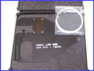 |
Model No. LPD-600
Log
Periodic Antenna
Frequency
Range:
600 MHz to 18 GHz
|
General Description
Log Periodic Dipole
Array (LPDA)
The geometrical configuration of the Log Periodic
antenna enables the characteristics to repeat periodically with the
logarithm of the frequency. Since the variation of performance
characteristics is small throughout one period, and because of the
repetitious nature of the antenna, the variation in performance will
be small throughout all periods. This results in an antenna with
input impedance, gain characteristic, and radiation patterns
essentially independent of frequency.
The LPD-600
is a lightweight, medium-gain, log periodic antennas. It is designed for reception or transmission of linear polarized radio
signals over the useful frequency range of 600 MHz to 18 GHz.
Precision construction of the elements results in excellent VSWR and
optimal phase relationship. The log periodic array design is
broadband with 50 ohm nominal impedance and a unidirectional
radiation pattern. It is compact, rugged, and weather resistant.
The antenna incorporates a handle, cable strain relief, and a ¼”-20
threaded insert for mounting on a camera tripod.
The
antenna is constructed of lightweight, copper clad PC board and
corrosion-resistant aluminum providing years of trouble free
performance. It is manufactured on FR4 .063” fiberglass
board, is triangular in shape, and has a transposed strip line
feed arrangement which provides an end fire pattern. The
maximum gain is off the tip of the structure in the direction of the
boom axis.
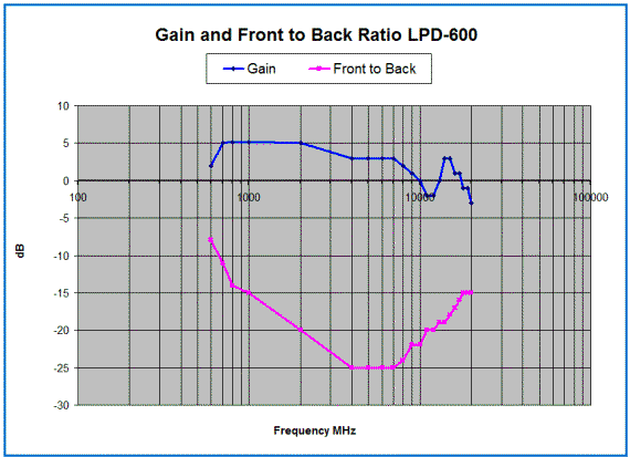
The gain of the antennas vary across the band
from 0 dBi to +6 dBi. A good front-to-back ratio is maintained at
about 8 to 30 db which provides a unidirectional radiation pattern
useful for radio direction finding. Representative gain,
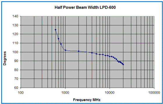
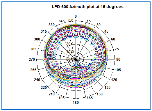
front-to-back, half power beam width and radar pattern curves are
shown below.
Transmitting power is limited primarily by the
power dissipation capability of the circuit board.
Do
not exceed 1/2 Watt CW input power. Exercise caution when applying
power if the antenna housing is wet.
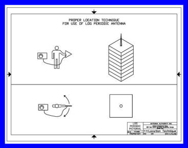
Examples of how to use the Portable Log Periodic Antenna.
The log periodic antenna is linearly polarized. Hold the
antenna vertical, for vertical polarized signals. Typically
this will be a whip antenna and your signals will be vertical.
Hold the antenna horizontal for horizontal signals. Since
circular polarized signals have both polarizations it does not
matter how you orient the antenna.
Swing the antenna back
and forth in azimuth across the suspect target location and look for
a maximum in the signal level. The log periodic antenna has a
broad pattern so there will not be a direct sharp peak - it will
cover 90 degrees or more. The target location will be in the
middle of the broad peak. For horizontally polarized signals,
it will most likely be easier to attempt to null the signal from the
back of the antenna, rather than seeking the maximum peak.
If the receiver has the AGC turned on it will be more difficult
because the receiver tries to hold the signal level constant.
Most radios do not allow you to turn off the AGC. If the
target signal is FM it will be even more difficult with a receiver
because in the FM mode most receivers use limiting to hold the level
at a constant. For that reason, a spectrum analyzer will likely be a
better choice for displaying the signal level visually instead of
trying to hear it
aurally.
You should also always keep the
antenna balanced with your body (see below) due to its close
proximity.
ELECTRICAL SPECIFICATIONS
Frequency Range: 600 MHz to 18 GHz
Radiation Pattern: Unidirectional in the H and E
Front-to-Back Ratio: 8 to 30 dB
Power Gain: 0 to +6 dBi
Impedance: 50 Ohm, nominal
VSWR: 1.5: 1 max
Transmitting Power: 1/2 Watt CW
Max
MECHANICAL SPECIFICATIONS
Dimensions: 12” X 9”
Weight:
7 oz without cabling
Mounting Hand Held with ¼”-20 threaded insert for camera tripod
Material: FR-4, double sided 0.063 inch thick 2 oz. copper
MAINTENANCE AND TROUBLE-SHOOTING
The
design of the LPD-600 is such that little or no
maintenance is required under normal usage. The housing should
be kept reasonably clean and dry and the connector must be free of
any obstruction.
If the antenna is suspected of failure,
some simple tests will usually isolate the problem. First,
visually inspect the connector at the rear and be sure the cabling
is seated properly. Any unseen damage to the connector or feed
line may be revealed using an Ohm meter. The center pin of the
connector to shield of the SMA should be about 50 ohms. Field
repairs can be accomplished as necessary or return the product for
service.
ORDERING INFORMATION
Antenna Kit:
Model No. LPD-600
Kit contains
Antenna LPD-600
Coax Cable with SMA fittings
Waterproof Shipping Case
Manual
Downloadable Manual in
PDF form for LPD-600
One year warranty on parts and labor
Specifications subject
to change without notice
Printed in U.S.A. Copyright
6/18/2015
Ferrel Bentley:
President: Antenna Authority Inc: Phone
770-577-7969 email Ferrel@dfAntennas.com
|